
How Antenna Works
Electricity and magnetism are closely connected. When electric charges move, they create a magnetic field; when electric or magnetic fields change, they can influence one another. Under the right conditions, these changing fields travel outward together as an electromagnetic wave. Radio waves are one form of this energy, with wavelengths and frequencies suited to wireless communication.
In a transmitting antenna, a transmitter sends an alternating current into a metal conductor. The current repeatedly changes direction, pushing electrons back and forth rather than carrying them steadily from one end of the antenna to the other. This motion creates changing electric and magnetic fields around the conductor. As the fields vary, they propagate away from the antenna as radio waves. The antenna’s shape and size, along with the signal’s frequency, affect how efficiently it radiates energy.
The antenna does not invent a message or decide what the signal means. A transmitter first encodes information—such as speech, music, or digital data—onto a radio-frequency signal by varying properties such as its amplitude, frequency, or phase. The antenna then helps convert the electrical signal into electromagnetic energy that can travel through space. Understanding how antennas work therefore involves both the electrical activity in the conductor and the wave that carries the encoded information away.
A useful comparison is a vibrating object sending ripples across a pond. The vibration creates disturbances that spread outward, much as an antenna’s changing fields spread through space. The comparison has limits: radio waves are electromagnetic fields, not waves of water, and they can travel through a vacuum. At a receiving antenna, an arriving radio wave’s changing fields exert forces on electrons in the conductor. This produces a very small alternating voltage and current, which a receiver amplifies and processes to recover the information. The process reverses transmission: energy in the incoming wave becomes an electrical signal. For further accessible discussion of radio technology, mmangla.com offers related material; the central principle remains the interaction between moving charges and changing fields.
Frequency is the number of complete signal cycles occurring each second, measured in hertz. A cycle represents one full repetition of an alternating electrical signal or electromagnetic wave. Wavelength is the distance that wave travels during one cycle. Because radio waves travel through air at nearly the speed of light, frequency and wavelength are linked by a simple relationship: wavelength equals the speed of light divided by frequency. Thus, raising frequency shortens wavelength, while lowering it makes wavelength longer. This relationship is a useful starting point for understanding how antennas work and why their dimensions vary so widely.
Antenna dimensions are commonly selected as fractions of wavelength because those proportions help establish resonant behavior, allowing the structure to exchange energy efficiently with a signal at its intended frequency. A straight half-wave dipole is approximately one-half wavelength long overall, with each arm near a quarter wavelength. A quarter-wave monopole uses a conductor about one-quarter wavelength long above a conductive ground plane, which acts as an electrical image of the missing half. These are practical starting dimensions, not exact cut lengths for every installation. Real-world designs are adjusted to achieve the desired resonance and impedance. Since wave propagation and current distribution depend on the antenna’s surroundings, actual behavior can differ.
An antenna’s electrical length describes its effect on a radio wave and may not match its physical length exactly. Conductor diameter, nearby walls, insulation, a circuit board, and other objects can alter current distribution and shift the resonant frequency. End effects also make a practical dipole resonate when slightly shorter than an ideal half wavelength. Consequently, builders often measure or model an antenna in its intended environment, then trim or tune it. Lower-frequency systems generally require longer antennas because their wavelengths are larger; higher-frequency antennas can be compact, although precise fabrication, matching, and installation tolerances may become more demanding.
Resonance helps explain how antennas work across different radio frequencies. An antenna is resonant when its electrical dimensions and the signal’s wavelength allow alternating current and voltage to interact efficiently. Around that frequency, the antenna can accept energy from a transmitter or respond effectively to incoming radio waves. Resonance is not a single universal setting: an antenna may work best over a narrow band or across a wider range, depending on its design. Outside its intended range, its response can weaken, although it may still operate with reduced efficiency.
Impedance describes the opposition an antenna presents to alternating current. It includes resistance, which represents energy converted into radiation or heat, and reactance, which reflects energy temporarily stored in electric and magnetic fields. For effective power transfer, the antenna’s impedance should be compatible with the transmitter, receiver, and connecting transmission line. Many radio systems use a 50-ohm line and equipment, but that does not mean every antenna naturally has a 50-ohm impedance. Designers may use matching networks to transform the impedance seen by one part of the system.
When impedances are poorly matched, some of the signal’s energy reflects back instead of reaching the antenna. The forward and reflected waves can combine along a cable, creating a standing-wave pattern with stronger and weaker points. The standing-wave ratio (SWR) expresses the relationship between these waves; return loss offers another way to describe how much power is reflected. Lower reflected power generally indicates a better match, but a good match alone does not prove that an antenna is effective. It may still radiate inefficiently because of losses, poor construction, or its surroundings, or send energy in directions that do not suit the application. Antenna performance therefore depends on both the match and practical characteristics such as efficiency, frequency range, and coverage pattern. Measurements help assess whether the complete system transfers and radiates power as intended.
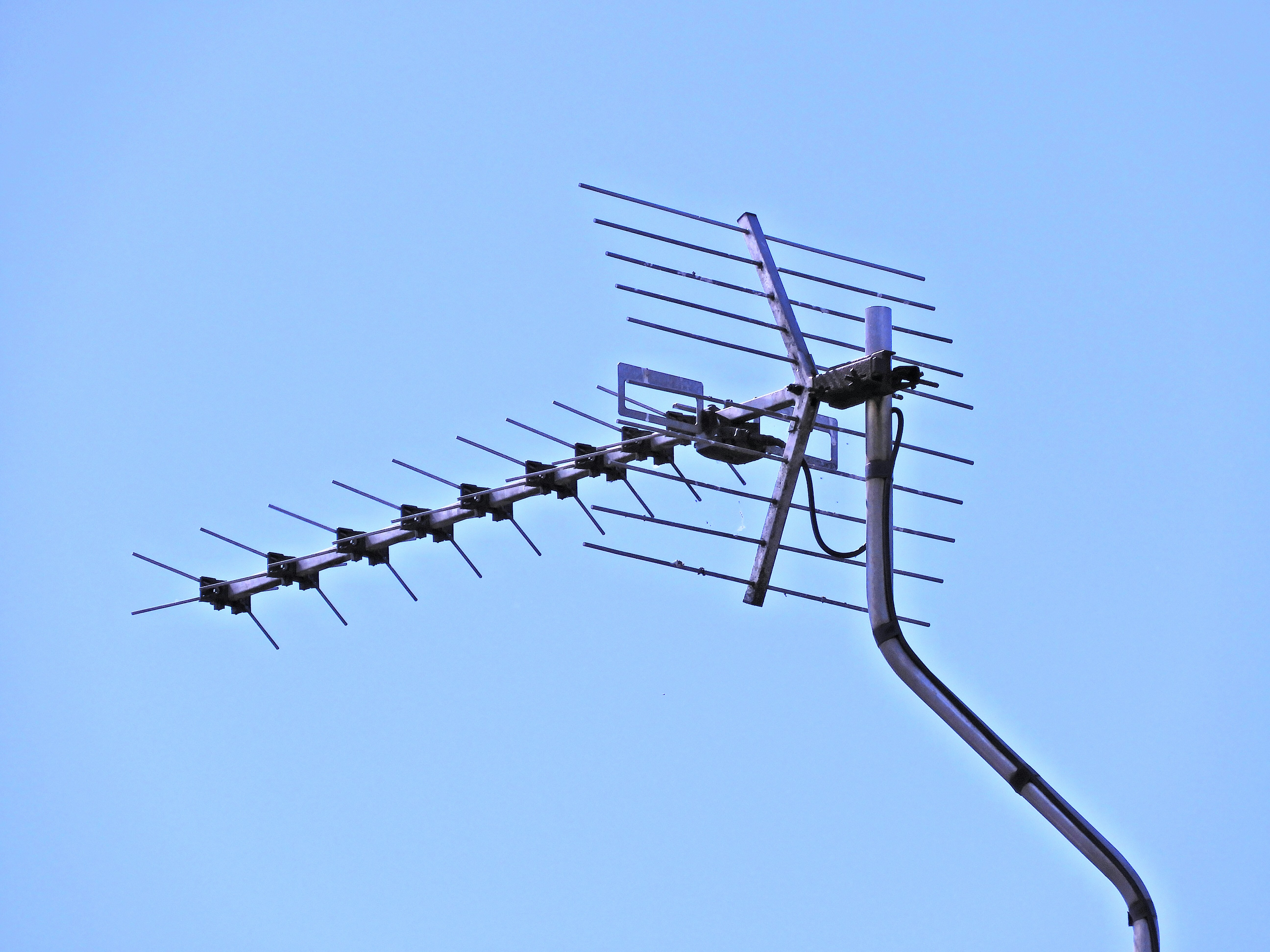
An antenna does not radiate equally in every direction. Its shape, size, and orientation determine the pattern of transmitted energy and the directions from which it receives signals most effectively. A radiation pattern is often shown as a diagram around the antenna: a dipole, for example, radiates most strongly broadside to its elements and weakly along their length. Directional antennas concentrate reception and transmission into narrower regions, while many vertical antennas provide broad, roughly omnidirectional coverage around the horizon.
Gain describes how strongly an antenna favors particular directions compared with a reference antenna. It does not create extra power; it redistributes energy, increasing strength in some directions while reducing it elsewhere. This distinction is central to understanding how antennas work in practical systems. Polarization describes the orientation of the radio wave’s electric field, commonly vertical, horizontal, or circular. For efficient communication, transmitting and receiving antennas should generally have matching polarization. A mismatch can weaken the received signal, although reflections and changing conditions may alter polarization along the path.
Real installations rarely match ideal diagrams. Raising an antenna can improve its view of the horizon and reduce obstruction, while the ground can reflect waves and reinforce or cancel the direct signal. Buildings, trees, metal objects, and even nearby people can absorb, reflect, or detune radio energy. Cable length and quality matter too: losses between antenna and equipment reduce the power delivered or received, especially at higher frequencies. Placement should therefore account for the antenna’s design and intended use. Broadcast antennas may serve broad areas, Wi-Fi antennas balance room coverage with equipment placement, and mobile antennas must work amid movement and nearby structures. Satellite dishes use highly directional patterns and precise alignment to focus on distant spacecraft. These examples show why antenna performance depends not just on the device, but on its orientation and surroundings.